
Lancia Rally 037: L'ultima posteriore.
Lancia Rally 037: The last rear-wheel drive
.
.


Lancia Rally 037. Nata nel periodo d'oro delle competizioni rallystiche con il solo scopo di sostituire la gloriosa Fiat 131 Abarth gruppo 4 che nel 1980 regala il terzo titolo costruttori alla Fiat. Impresa non facile. In considerazione anche che nel 1982 entreranno in vigore i nuovi regolamenti del Gruppo B.
A Torino, in Corso Marche sede della Abarth, c'è del fermento. Dopo varie ipotesi, l'Ing Sergio Limone coordinatore tecnico del reparto corse, sceglie di utilizzare la cellula della Lancia Montecarlo (già disponibile e che sta per uscire di produzione) per la produzione minima dei 200 esemplari previsti per l'omologazione. Il nome del nuovo progetto è SE037. Pininfarina costruisce le 200 scocche previste. Si dice che alla fine siano stati prodotti 207 esemplari. Ma in questi casi (come avverrà per la Delta S4) sono dati difficili da verificare. Probabilmente le auto costruite sono un numero inferiore. Ipotesi. Ma questo non fa che aumentare il fascino e il mito legato alle vetture di Gruppo B di quel periodo. La Lancia Rally 037 (che poi nel cuore degli appassionati e per il grande pubblico sarà solo 037) ottiene l'omologazione per il Gruppo B il 1 Aprile 1982. I carburatori del veicolo stradale sono sostituiti con iniezione meccanica Kugelfisher e ci sono altre modifiche. Il debutto non è però perfetto. Già dal 1 Agosto 1982 il regolamento prevede di poter effettuare modifiche e nasce la EVO 1 che risulterà già competitiva. Il Volumex (compressore volumetrico) viene sostituito con un analogo ma più grande (si passa da un R10 a un R18) e si inserisce un sistema di sfiato dell'aria compressa generata dal compressore che, al momento del rilascio dell'acceleratore, viene dispersa per evitare che si crei una contropressione di ritorno. Quello che però interessa a noi in questo contesto, avviene dal 1 Gennaio 1984. Nasce la EVO 2. Il motore è portato da 1995 a 2111 cc, viene modificato tutto il sistema di aspirazione con un nuovo collettore ed un nuovo filtro dell'aria. Il sistema di sfiato dell'aria compressa non disperde più nel vuoto ma convoglia il flusso d'aria verso il nuovo radiatore dell'olio del cambio inserito in un box metallico posizionato sulle traverse centrali. Al cambio ZF viene quindi aggiunta una pompa per collegare il cambio stesso al radiatore (ben visibile nella parte finale sotto la marmitta). Con altre modifiche meno in vista (ad eccezione dell'eliminazione del paraurti posteriore) la 037 arriva ad avere circa 310 CV. Con i colori ufficiali parteciperà al mondiale 1984 e 1985 per poi essere sostituita dalla S4. Ma questa è un 'altra storia. Dal punto di vista modellistico, questo transkit è utilizzabile su tutti i kits hasegawa 1/24. Devono essere però auto iscritte a gare svolte dal 01/01/1984 in poi. Nel periodo che va dal 01/08/1982 al 31/12/1983 si parla di EVO 1. Presto sarà disponibile anche questa versione con le dovute modifiche.
Lancia Rally 037. Born in the golden age of rally racing with the sole purpose of replacing the glorious Fiat 131 Abarth group 4 which in 1980 gave Fiat its third constructors title. Not an easy undertaking. Also considering that in 1982 the new Group B regulations will come into force.
In Turin, in Corso Marche, the Abarth headquarters, there is excitement. After various hypotheses, Engineer Sergio Limone, technical coordinator of the racing department, chooses to use the Lancia Montecarlo cell (already available and which is about to go out of production) for the minimum production of the 200 specimens expected for homologation. The name of the new project is SE037. Pininfarina builds the planned 200 bodies. It is said that 207 examples were eventually produced. But in these cases (as it will happen for the Delta S4) data is difficult to verify. There are probably fewer cars built. Hypothesis. But this only adds to the fascination and myth associated with the Group B cars of that period. The Lancia Rally 037 (which later in the hearts of enthusiasts and for the general public will only be 037) obtains homologation for Group B on 1 April 1982. The carburetors of the road vehicle are replaced with Kugelfisher mechanical injection and there are other modifications. However, the debut is not perfect. Already from 1 August 1982 the regulation provides for the possibility of making changes and the EVO 1 is born, which will already be competitive. The Volumex (volumetric compressor) is replaced with a similar but larger one (it switches from an R10 to an R18) and a system for venting the compressed air generated by the compressor is inserted which, when the accelerator is released, is dispersed to avoid creating a back pressure. What interests us in this context, however, has taken place since January 1, 1984. The EVO 2 is born. The engine is brought from 1995 to 2111 cc, the entire intake system is modified with a new manifold and a new air filter. The compressed air vent system no longer disperses in the vacuum but conveys the air flow to the new gearbox oil cooler inserted in a metal box positioned on the central crosspieces. A pump is then added to the ZF gearbox to connect the gearbox itself to the radiator (clearly visible in the final part under the muffler). With other less visible changes (with the exception of the elimination of the rear bumper) the 037 comes to have around 310 hp. With the official colors it will participate in the 1984 and 1985 world championships and then be replaced by the S4. But this is another story. From a modeling point of view, this transkit can be used on all 1/24 hasegawa kits. However, they must be cars registered for races held from 01/01/1984 onwards. In the period from 01/08/1982 to 31/12/1983 we talk about EVO 1. Soon this version will also be available with the necessary changes.
EVO 2 ENGINE 1/24


 |

IL TRANSKIT / THE TRANSKIT
Questo transkit permette di realizzare la versione EVO 2 della Lancia Rally 037. I vari kits Hasegawa in commercio non presentano nessuna distinzione tra le due versioni se non la possibilità di installare la parte bassa del paraurti posteriore presente solo nella EVO 1. Il transkit è composto da 37 parti (delle quali, come vedremo, 3 opzionali).
This transkit makes it possible to create the EVO 2 version of the Lancia Rally 037. The various Hasegawa kits on the market do not present any distinction between the two versions except for the possibility of installing the lower part of the rear bumper present only in EVO 1. The transkit is composed of 36 parts (of which, as we shall see, 3 are optional).


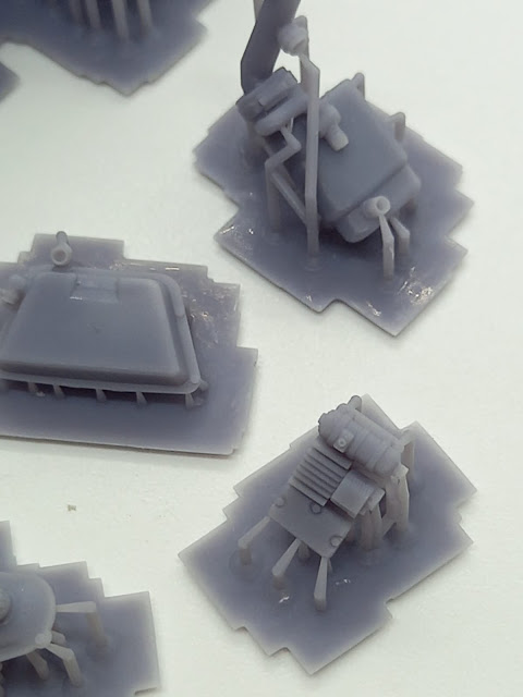

Per separare agevolmente i pezzi dai supporti di stampa è necessario utilizzare delle tronchesine piatte da modellismo e procedere senza fretta tagliando un supporto alla volta. Quando si separano le parti più fini dai supporti è necessario usare molta cautela. IN CASO DI ROTTURA del pezzo si può riparare con colla cianoacrilica. Consiglio ti ripulire costantemente il piano di lavoro dai supporti una volta rimossi altrimenti sarà difficile individuare l'eventuale parte rotta specialmente se di piccole dimensioni.
Le parti, una volta rimosse dai supporti di stampa, potranno essere rifinite con carta abrasiva ed eventualmente stuccate con qualsiasi tipo di stucco da modellismo. Un consiglio che posso dare è quello di ripulire spesso con un pennellino piatto e della semplice acqua, le zone sulle quali stiamo lavorando. Questo aiuterà molto ad eliminare le polveri prodotte con la carta abrasiva e vedere chiaramente il livello di pulizia ottenuto. Questo transkit è realizzato con resina foto-indurente water-washable. Quindi non sono stati utilizzati prodotti chimici (come alcool isopropilico o acetone per la fase di post stampa) ma della semplice acqua. Se si notano delle piccole zone sui pezzi o sui supporti che appaiono come "bagnate" non c'è da allarmarsi. Sono particelle di acqua rimaste sul pezzo al momento della polimerizzazione nel forno UV (fase di post-stampa) che sono solo superficiali e scompariranno con una lieve passata di carta abrasiva. Ricordiamoci però che il prodotto è comunque una resina e quindi si devono utilizzare tutte le cautele necessarie mentre si usa la carta abrasiva (mascherina/occhiali eccetera). Le componenti si assemblano con colla CIANOACRILICA. Non utilizzare colla per modellismo o vinilica. Una volta assemblati i pezzi, o alcune parti tra loro, prima di colorare è buona norma lavare il pezzo con acqua e detersivo per piatti ed asciugarlo. E' NECESSARIO UTILIZZARE UN PRIMER da modellismo per due motivi. Il primo è che con il primer verranno evidenziati i dettagli altrimenti poco visibili ad occhio nudo a causa della composizione della resina ed il secondo in quanto altrimenti la successiva verniciatura potrebbe avere problemi di adesione.
To easily separate the pieces from the print supports, it is necessary to use flat modeling cutters and proceed without haste, cutting one support at a time. When separating the finer parts from the supports you need to be very careful. IN CASE OF BREAKAGE of the piece it can be repaired with cyanoacrylate glue. I advise you to constantly clean the worktop from the supports once removed, otherwise it will be difficult to identify any broken part, especially if small.
The parts, once removed from the print supports, can be finished with sandpaper and possibly filled with any type of modeling putty. One piece of advice I can give is to often clean the areas we are working on with a flat brush and plain water. This will help a lot to eliminate the dust produced by the sandpaper and to clearly see the level of cleanliness achieved. This transkit is made with water-washable light-curing resin. So no chemicals were used (such as isopropyl alcohol or acetone for the post-printing phase) but simple water. If you notice small areas on the pieces or on the supports that appear as "wet" there is no need to be alarmed. They are particles of water left on the piece at the time of polymerization in the UV oven (post-printing phase) which are only superficial and will disappear with a light pass of sandpaper. However, remember that the product is still a resin and therefore all necessary precautions must be used while using the abrasive paper (mask / glasses etc.). The components are assembled with CYANOACRYLIC glue. Do not use modeling or vinyl glue. Once the pieces, or some parts together, have been assembled, before coloring it is a good idea to wash the piece with water and dish soap and dry it. IT IS NECESSARY TO USE A PRIMER for modeling for two reasons. The first is that with the primer the details otherwise not very visible to the naked eye will be highlighted due to the composition of the resin and the second because otherwise the subsequent painting could have adhesion problems.


IL KIT HASEGAWA : modifiche preliminari
THE HASEGAWA KIT: preliminary changes
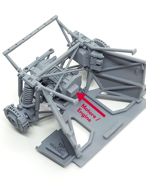
Prima di cominciare l'assemblaggio del transkit è necessario apportare delle modifiche allo chassis del kit Hasegawa in quanto tutte le parti del motore e del traliccio saranno completamente sostituite con i componenti di resina. La prima operazione consiste nell'eliminazione della slitta inferiore (basamento su cui appoggia il motore) e dei relativi braccetti di attacco.
Before starting the assembly of the transkit it is necessary to make some changes to the chassis of the Hasegawa kit as all the parts of the engine and the trellis will be completely replaced with the resin components. The first operation consists in eliminating the lower slide (base on which the motor rests) and the relative attachment arms.
Le parti in rosso devono essere eliminate mentre le zone in verde (le due alette triangolari) sono mantenute.
The parts in red must be eliminated while the areas in green (the two triangular wings) are kept


Una volte rimosse le parti rimarrà un sottile strato di plastica all'interno del rettangolo verde evidenziato nella seguente foto che deve essere eliminato
Once the parts are removed, a thin layer of plastic will remain inside the green rectangle highlighted in the following photo which must be eliminated

Anche i pin evidenziati in rosso devono essere rimossi in quanto non saranno più necessari e creano un ostacolo.
Pins highlighted in red also need to be removed as they will no longer be needed and create an obstacle.

Alla fine delle operazioni lo chassis hasegawa si presenterà cosi:
At the end of the operations the hasegawa chassis will look like this:


Una volta rimossi i supporti di stampa dal nuovo telaio è importante togliere ogni imperfezione sotto le linguette indicate in foto. Per motivi di resistenza strutturale ho preferito stampare qualche decimo di millimetro in più in questa zona. Con una limetta si procede come illustrato (anche assottigliando la plastica sul kit hasegawa dove precedentemente erano posizionati i pin circolari rimossi).
Once the print supports have been removed from the new frame, it is important to remove any imperfections under the tabs indicated in the photo. For reasons of structural strength, I preferred to print a few tenths of a millimeter more in this area. With a file proceed as illustrated (also by thinning the plastic on the hasegawa kit where the circular pins removed were previously positioned).

Adesso è possibile verificare il posizionamento del nuovo telaio. Non preoccupatevi se, una volta rimossi i supporti di stampa, il telaio tende a flettere leggermente verso l'interno. A causa delle dimensioni dei tubi e della forma del pezzo è normale. Anzi l'elasticità della resina sarà fondamentale durante le varie fasi di lavoro. Una volta installate tutte le componenti il telaio prenderà la forma corretta. Nella parte bassa del telaio è presente un pin rettangolare che serve a conferire la giusta posizione al pezzo. Il telaio dovrà essere installato come nella foto seguente utilizzando il pin rettangolare e i due piccoli incastri laterali. Inoltre saranno utilizzati i due fori presenti nel kit come riferimento ed ulteriore ancoraggio dei tubi.
Now you can check the positioning of the new frame. Don't worry if the frame tends to flex slightly inward after the print media is removed. Due to the size of the tubes and the shape of the workpiece this is normal. Indeed, the elasticity of the resin will be essential during the various stages of work. Once all the components have been installed, the frame will take the correct shape. In the lower part of the frame there is a rectangular pin which serves to give the right position to the piece. The frame must be installed as in the following photo using the rectangular pin and the two small lateral joints. Furthermore, the two holes in the kit will be used as a reference and further anchoring the pipes.


Il telaio sarà fissato in modo definitivo con colla solo alla fine della costruzione. Per rimuovere il pezzo è sufficiente esercitare una lieve pressione sul pin rettangolare e tirare verso l'esterno. Come dicevamo l'elasticità della resina consente di installare e rimuovere senza problemi la parte. Quando sarà posizionato il motore, non sarà più possibile avere accesso dall'alto e , per rimuovere il retrotreno, si dovrà procedere dal sotto con molta cautela per non rovinare l'eventuale colorazione.
The frame will be fixed permanently with glue only at the end of the construction. To remove the piece, simply exert a slight pressure on the rectangular pin and pull outwards. As we said the elasticity of the resin allows you to install and remove the part without problems. When the engine is positioned, it will no longer be possible to have access from the top and, to remove the rear axle, you will have to proceed from underneath with great caution so as not to damage any color.


Un'altra modifica da apportare è la foratura sulla carrozzeria delle bocchette di rifornimento in quanto saranno sostituite dalle parti in resina. Non verranno utilizzati tappi come nel kit hasegawa ma saranno i serbatoi della benzina, come nella realtà, a sporgere fuori dalla carrozzeria. Per le dimensioni del foro fare riferimento al nuovo serbatoio.
Another change to be made is the drilling on the bodywork of the filler vents as they will be replaced by the resin parts. Caps will not be used as in the hasegawa kit but it will be the petrol tanks, as in reality, that protrude out of the bodywork. For hole dimensions refer to the new tank.


MONTAGGIO DELLE PARTI / ASSEMBLY OF PARTS
La costruzione inizia con il fissaggio del cambio sul telaio. E' il punto di partenza con un riferimento ben preciso in modo da garantire un corretto sviluppo del progetto. Sul telaio è presente un pin rettangolare (colorato in rosso nella foto) sul quale andrà posizionato il cambio. Il forellino che si vede nel cambio è servito solo per inserire un supporto per stendere il primer ad aerografo. Anche le due piastre di attacco (evidenziate nel cerchio rosso) hanno la loro posizione precisa.
Construction begins with attaching the gearbox to the frame. It is the starting point with a precise reference in order to guarantee a correct development of the project. On the frame there is a rectangular pin (colored red in the photo) on which the gearbox will be positioned. The small hole that you see in the gearbox was only used to insert a support to spread the airbrush primer. The two attachment plates (highlighted in the red circle) also have their precise position.


Un altro pezzo fondamentale per dare la forma corretta al kit è il telaietto centrale di rinforzo con tubi incrociati. Anche in questo caso la flessibilità della resina ci permetterà di installare il pezzo senza problemi. Una volta posizionato su un lato basterà effettuare una lieve forza sul lato opposto per ottenere il giusto posizionamento. ATTENZIONE: il telaietto ha un orientamento ben preciso. La parte contrassegnata con una piccola protuberanza deve essere rivolta verso la parte anteriore del veicolo!
Another key part to give the kit the correct shape is the central reinforcement frame with crossed tubes. Also in this case the flexibility of the resin will allow us to install the piece without problems. Once positioned on one side it will be sufficient to apply a slight force on the opposite side to obtain the right positioning. ATTENTION: the subframe has a precise orientation. The part marked with a small protuberance must face the front of the vehicle!


Si può adesso installare il serbatoio in vetroresina a forma di trapezio che è posizionato nella parte sinistra del telaio. In questo caso non ci sono incastri. Ma la forma del pezzo stesso indica dove deve essere collocato come evidenziato nelle foto seguenti. Il pannello con la bobina e le centraline invece ha il suo pin di riferimento per cui la scelta è obbligata.
It is now possible to install the fiberglass tank in the shape of a trapezoid which is positioned on the left side of the frame. In this case there are no joints. But the shape of the piece itself indicates where it needs to be placed as highlighted in the photos below. The panel with the coil and the control units instead has its own reference pin so the choice is mandatory.


GRUPPO FRENI SOSPENSIONI / SUSPENSION - BRAKE GROUP
Il gruppo sospensioni / freni è formato da 3 parti distinte più un' ulteriore quarta parte di uso opzionale. Sono infatti presenti il mozzo della ruota (destro e sinistro speculari e che hanno un preciso orientamento), la molla dell'ammortizzatore, il disco del freno comprensivo delle due pinze (anche questo da orientare nel modo corretto) e un fondello opzionale con i prigionieri di fissaggio del cerchio nel caso si voglia rappresentare il veicolo senza cerchio. Se invece si installa la ruota, il fondello non deve essere utilizzato. Il mozzo ha tre incastri per il corretto posizionamento. Il primo è quello inferiore idoneo a collegarlo ai braccetti del trapezio come nella realtà. Ci sono poi gli incastri del doppio stelo degli ammortizzatori e quelli della barra a forma di "U". Prima di tutto però si devono installare i semiassi posizionandoli come nella foto (la cuffia più grande deve essere connessa al cambio). Inoltre è opportuno inserire la molla (senza colla) sul mozzo prima di posizionarlo.
The suspension / brake unit is made up of 3 distinct parts plus an additional fourth part for optional use. In fact, there are the wheel hub (right and left mirrored and which have a precise orientation), the shock absorber spring, the brake disc including the two calipers (also to be oriented in the correct way) and an optional bottom with the studs. fixing the rim if you want to represent the vehicle without a rim. If, on the other hand, you install the wheel, the bottom must not be used. The hub has three joints for correct positioning. The first is the lower one suitable for connecting it to the arms of the trapezoid as in reality. Then there are the joints of the double shock absorber stem and those of the "U" -shaped bar. First of all, however, the drive shafts must be installed by positioning them as shown in the photo (the larger boot must be connected to the gearbox). It is also advisable to insert the spring (without glue) on the hub before positioning it.


Se si desidera presentare l'auto senza la ruota si può utilizzare il fondello. Conviene incollarlo al disco del freno prima della colorazione e stuccare la giuntura.
If you want to present the car without the wheel, you can use the caseback. It is advisable to glue it to the brake disc before coloring and fill the joint.

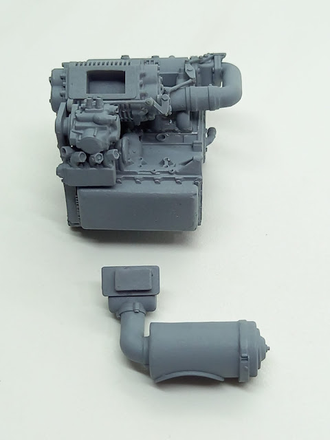
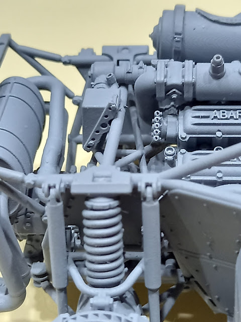
GRUPPO MOTORE / ENGINE GROUP
Il primo componente da aggiungere al motore è il gruppo aspirazione / volumex elemento tipico della versione EVO 2. il collegamento è obbligato da 4 pin sul collettore di aspirazione che devono essere inseriti nei 4 fori presenti sul lato sinistro della testa del motore. Si presti attenzione al collegamento del leveraggio che collega la pompa di iniezione della benzina con il meccanismo di leve inserito sul volumex che manovra l'apertura della valvola a tamburo.
The first component to add to the engine block is the suction / volumex group, a typical element of the EVO 2 version. The connection is forced by 4 pins on the intake manifold which must be inserted into the 4 holes on the left side of the engine head. Pay attention to the linkage of the linkage that connects the petrol injection pump with the lever mechanism inserted on the volumex which operates the opening of the drum valve.


Si installa poi il filtro dell'aria. Anche in questo caso c'è un incastro che vincola il posizionamento delle parti.
The air filter is then installed. Also in this case there is a joint that constrains the positioning of the parts.
 |
Si collocano adesso motorino di avviamento e filtro dell'olio come in foto.
The starter motor and oil filter are now installed as shown in the photo.


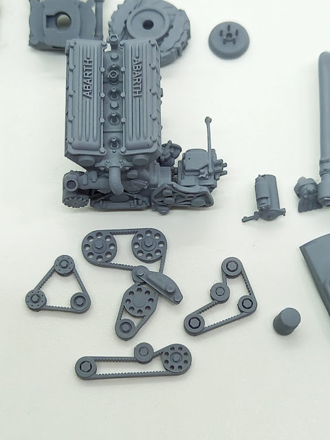
Per le pulegge (e relative cinghie di trasmissione) ho suddiviso, come nella realtà, in 4 gruppi distinti da inserire con la giusta sequenza:
1 cinghia della testa (distribuzione)
2 cinghia pompe benzina/olio
3 cinghia pompa acqua/alternatore
4 cinghia volumex
Sul blocco motore sono stampati i riferimenti necessari. Si noti che la puleggia dell'albero motore ha sopra di se altre due pulegge per un totale di tre. Anche la puleggia di moto del gruppo pompe è sovrapposta alla puleggia di rimando del gruppo testa.
For the pulleys (and related transmission belts) I divided, as in reality, into 4 distinct groups to be inserted with the right sequence:
1 head strap (distribution)
2 petrol / oil pump belt
3 water pump / alternator belt
4 belt volumex
The necessary references are printed on the engine block. Note that the crankshaft pulley has two other pulleys above it for a total of three. The motion pulley of the pump group is also superimposed on the return pulley of the head group.


Si può adesso montare lo spinterogeno nella sua tipica posizione inclinata utilizzando l'apposito foro
The distributor can now be mounted in its typical inclined position using the appropriate hole


Si installa quindi il collettore di scarico. Oltre ai 4 pin sul collettore e relativi 4 fori sul blocco motore, come nella realtà, è presente una staffetta che deve essere collegata come mostrato in foto.
The exhaust manifold is then installed. In addition to the 4 pins on the manifold and related 4 holes on the engine block, as in reality, there is a bracket that must be connected as shown in the photo.


COLLEGAMENTO MOTORE / CAMBIO
ENGINE / GEARBOX CONNECTION
Per collegare il blocco motore al cambio è previsto un innesto che facilita l'installazione. Sarà sufficiente far combaciare le due parti. L'incastro è leggermente sovradimensionato per permettere dei lievi aggiustamenti qualora ce ne fosse la necessità. Da notare che il motore è ruotato di circa 17° rispetto al piano di appoggio del cambio (come nella realtà). Per questo motivo anche l'incastro nel blocco motore è ruotato. Come sempre è buona norma verificare gli accoppiamenti delle varie parti prima di posizionarle definitivamente.
A coupling is provided to connect the engine block to the gearbox which facilitates installation. It will be enough to match the two parts. The joint is slightly oversized to allow for slight adjustments if necessary. It should be noted that the engine is rotated about 17 ° with respect to the gearbox support plane (as in reality). For this reason, the interlocking in the engine block is also rotated. As always, it is a good idea to check the couplings of the various parts before positioning them definitively.
Una volta allineato e posizionato il blocco motore con il cambio, si procede ad installare il serbatoio dell'olio e la pompa di aspirazione del carburante nella loro posizione. Il serbatoio dell'olio ha un doppio incastro che ne vincola la posizione mentre per la pompa del serbatoio benzina è previsto un appoggio sul telaio.
Once the engine block has been aligned and positioned with the gearbox, the oil tank and fuel suction pump are installed in their position. The oil tank has a double joint which binds its position while a support on the frame is provided for the fuel tank pump.


E' il momento di posizionare la valvola di scarico dell'aria compressa in eccedenza prodotta dal Volumex. Quando si alza il piede dall'acceleratore la valvola a tamburo si chiude e per evitare che l'aria compressa prodotta dal volumex abbia un rientro pericoloso nel volumex stesso viene scaricata all'esterno. Mentre nella versione EVO1 l'aria compressa era semplicemente dispersa, in questa configurazione l'aria compressa è convogliata fin dentro al box metallico posizionato sui tralicci centrali del telaio dove al suo interno è presente il radiatore dell'olio del cambio ZF con la funzione di raffreddamento. Nella EVO1 è assente il radiatore del cambio. La parte da collegare al Volumex ha un innesto circolare da inserire nell'apposito foro. Prima di incollarlo conviene trovare la giusta posizione del box sul traliccio. Il retro del box ha la forma ideale per inserirsi sul tubo del telaio quindi basta verificare la corretta inclinazione del box prima di incollare il tutto.
It is time to position the excess compressed air discharge valve produced by the Volumex. When you take your foot off the accelerator, the drum valve closes and to prevent the compressed air produced by the volumex from having a dangerous re-entry into the volumex itself, it is discharged to the outside. While in the EVO1 version the compressed air was simply dispersed, in this configuration the compressed air is conveyed right into the metal box positioned on the central pylons of the frame where inside there is the ZF gearbox oil cooler with the function of cooling down. In the EVO1 the gearbox radiator is absent. The part to be connected to the Volumex has a circular coupling to be inserted in the appropriate hole. Before gluing it, it is advisable to find the right position of the box on the trellis. The back of the box has the ideal shape to fit on the frame tube so just check the correct inclination of the box before gluing everything.

La marmitta può essere adesso collegata al collettore di scarico tramite il suo innesto ed alla staffetta di supporto sopra il cambio usando i due pin di riferimento.
The muffler can now be connected to the exhaust manifold through its coupling and to the support bracket above the gearbox using the two reference pins.


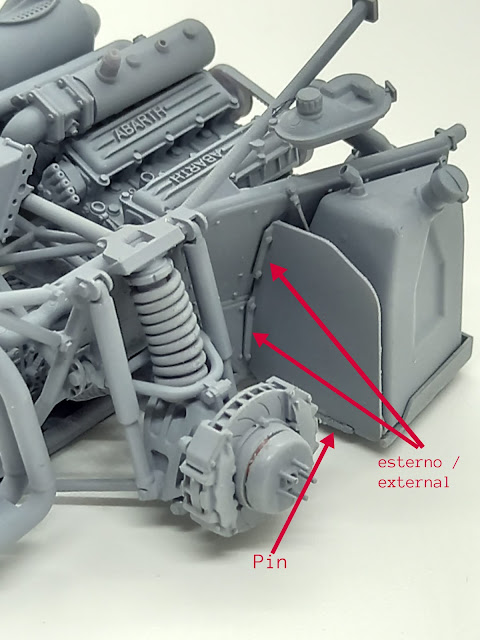
Si possono adesso installare le protezioni in kevlar dei serbatoi benzina. I due pezzi sono speculari. Le alette di fissaggio devono essere rivolte verso l'esterno cioè verso la ruota. La forma è studiata per aderire precisamente alle lamiere del telaio. Ci sono anche due innesti stampati se si desidera installare il tirante di rinforzo da realizzare in sprue stirato a caldo o con un realistico cavetto di metallo (per esempio una corda di chitarra).
You can now install guards in kevlar of petrol tanks. The two pieces are mirror. The fastening lugs should be directed towards the outside i.e. towards the wheel. The shape is designed to adhere precisely to the chassis plates. There are also two printed grafts if you want to install the reinforcing rod to be carried out in hot sprue ironed or with a realistic metal wire (for example, a guitar string).


SERBATOIO BENZINA / FUEL TANK
I due serbatoi devono essere posizionati correttamente utilizzando il riferimento stampato sul basamento. Il serbatoio di sinistra ha un piccolo e basso tappo assente sul serbatoio di destra. Dal momento che la parte terminale dei serbatoi deve essere inserita nella carrozzeria dell'auto, è necessario bloccare in maniere definitiva il transkit allo chassis del kit Hasegawa. A questo punto utilizzando colla vinilica o comunque a lenta essiccazione si installano i serbatoi e si posizionano con eventuali piccoli movimenti fino ad avere la perfetta corrispondenza con la carrozzeria del kit.
The two tanks must be positioned correctly using the reference printed on the base. The left tank has a small, low cap absent on the right tank. Since the end of the tanks must be inserted into the car body, it is necessary to permanently lock the transkit to the chassis of the Hasegawa kit. At this point, using vinyl glue or slow drying glue, the tanks are installed and positioned with any small movements until they have perfect correspondence with the body of the kit.


Ci sono infine i serbatoi dei liquidi da installare. Il più piccolo deve essere posizionato a sinistra direttamente sullo chassis del kit in corrispondenza del traliccio come in foto. Il serbatoio di destra, più grande, deve essere appoggiato da una parte sull'apposita sporgenza stampata sul tubo e dall'altra ancorato allo chassis.
Finally, there are the liquid tanks to be installed. The smaller one must be positioned on the left directly on the chassis of the kit in correspondence of the trellis as in the photo. The tank on the right, larger, must be placed on one side on the projection printed on the tube and on the other anchored to the chassis.


Il transkit prevede un ultimo pezzo di installazione facoltativa: il raccordo tra il cilindro del filtro dell'aria ed il lunotto posteriore in plexi trasparente della Lancia. Questo raccordo veniva utilizzato prevalentemente per le prove speciali su terra o comunque non asfaltate. Sarà il modellista a decidere se utilizzare questa parte in base all'auto da realizzare.
The transkit includes a final optional installation piece: the connection between the air intake cylinder and the Lancia's transparent plexi rear window. This link was mainly used for special tests on dirt, however not asphalted. The model maker will decide whether to use this part based on the car to be made.


Con questo ho concluso. Per qualsiasi informazione, dubbio o domande non esitate a scrivermi su questo blog o sul mio profilo FB:
Grazie a tutti per l'attenzione
Claudio.
With this I have concluded. For any information, doubts or questions do not hesitate to write me here or on my FB profile:
https://www.facebook.com/claudio.debellis.37/
Thanks everyone for your attention
Claudio.